Lubrication should be used
very sparingly and only applied where it is intended to be. Lubricating parts that
shouldn't be can cause erratic operation and oxidation of contact points. Two types of
lubricant are used in the Ericofon, compounded mineral oil and lithium grease. If some of
the names of parts in this list are unfamiliar to you, refer to the chassis assemblies in
"Ericofon Wiring Diagrams and Parts Lists". You will also find more information
on lubrication from the "Working On Your Ericofon" menu.
- Use compounded mineral oil on these parts...
- Standswitch Plunger Return Spring
- Gear teeth of the Main Gear
- Gear teeth of the Intermediate Gear
- Sliding surfaces of the Ratchet Spring on both sides of the Impulse Cam
- Main Spring
- Use Lithium Grease on these parts...
- Sliding surfaces on the Main Gear step for operation of the Pile-up lift Spring
- Bearing surfaces on the Standswitch Plunger
- Sliding surfaces on the Standswitch Plunger
- All shaft bearings in the Frame and Intermediate Spindle Bearing Plate
- Standswitch Plunger Retainer Clip where it contacts the Standswitch Plunger
In this section I will show you a simple method of lubricating your
Ericofon. This demonstration is very basic and covers the parts most likely to need
lubrication without having to do any serious disassembly work. In fact, very little work
is needed to do this "home version" of a "lube job".
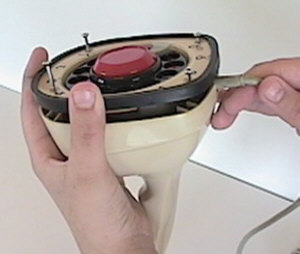 |
Removing
the shell
Start by
loosening (but not removing) the four screws in the dial face that hold the shell on. |
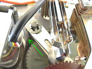 |
Removing
the standswitch
This is a tricky one that evades a lot of people. To remove the
Standswitch from the dial, you have to slide back the standswitch retainer clip on the
main spindle bearing plate. Reach in with a small screw driver and push back the clip and
the standswitch will pull right out.
|
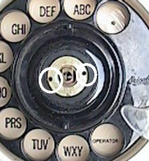 |
Removing
the finger wheel
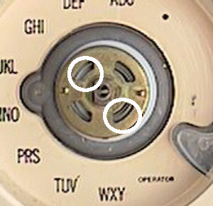
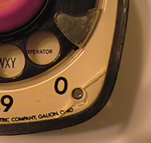
After removing
the Stand Switch, you can not remove the finger wheel. The finger wheel retaining
nut is removed by unscrewing it using a tool in the two holes shown.
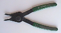
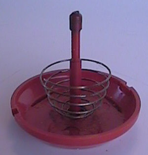
This is the tool I use to remove the fingerwheel nut. It's actually a "Retainer Ring
Pliers" and is a cheap tool you can buy at any hardware store. It works perfectly for
the job.
|
 |
Lubricating
the main spring
Once you have the fingerwheel off, you will see the mainspring and mainsping housing.
You could take it off to clean it and lube it, but I advise against it. Because of the age
and the tightness of the winding, they tend to break when allowed to relax (voice of
experience speaking here).
To lubricate the mainspring, just put a drop or two of mineral oil through two opposing
openings, and then give it full turn a few times to distribute the oil. |
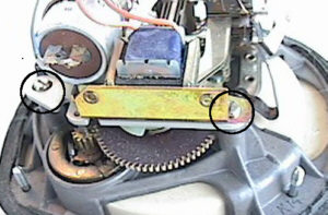 |
Removing
the bearing plate
To remove the bearing plate (and any assembly that may be attached to it),
remove the two screws (circled in the picture at left).
Lay any assembly that comes up from the plate back over out of the way. There's no need
to undo any wiring |
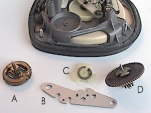 |
Here's a
picture of the individual parts. 'A' is the governor, 'B' is the bearing plate, 'C' is the
impulse cam, and 'D' is the intermediate gear assembly. |
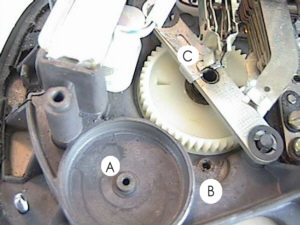 |
Lubricating
the chassis
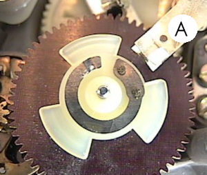
Make sure the governor
well 'A' and the spindle hole 'B' for the intermediate gear is clean. Put a drop of oil on
the standswitch retainer clip 'C', work it back and forth a couple times. Put a dab of
lithium grease on the bottom and top end of the governor spindle and put it back in place.
Don't get any grease or oil on the metal surfaces in the governor well! |
 |
Lubricating
the main gear
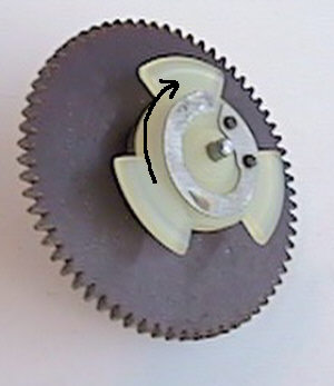
Clean the ends of the intermediate gear spindle and put a drop of oil on the top
part of the shaft for lubrication of the impulse cam. When putting the impulse cam back
on, be sure the lobes of the cam align with the metal "wings" on the top of the
gear.
Put some mineral oil on a rag and dab the rag on the teeth of the intermediate gear to
lightly oil them |
 |
Reinstalling
the impulse cam
Use the same rag with oil to rub the lobes of the impulse cam, but don't get
excess oil on them.
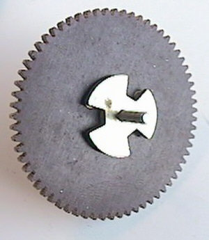
There is a right way and a wrong way to put the impulse cam back on the spindle. The
metal tab that lifts up into the air should be pointing clockwise.
If you put the impulse cam on upside down, it will not dial correctly. |
 |
Reinstalling
the main gear
Put a tiny dab of lithium grease on both ends of the intermediate gear spindle
and carefully jockey it back into place making sure that the impulse contacts 'A' are
between lobes of the impulse cam.
Place the bearing plate and any other assembly back in place and put the two screws
back in.
Give the dial a quick turn to make sure the impulse contacts are not touching any cam
lobes when at rest. If the contacts are touching the cam lobes, lift the gear assembly
high enough to dissengage the main gear and turn it a couple of degrees. |
 |
The
stand switch
Clean the plunger of the standswitch and put a couple drops of oil on it. You
can also see from this picture the correct direction for the spring.
When putting the fingerwheel nut back on, be sure it is nice and square with the end of
the spindle or it will cross thread. A sign of this is the fingerwheel will appear to
"wobble" when turned. If this happens, loosen the nut and start over. Don't
worry, it won't strip the threads if you accidently cross thread it. Snug the nut back on,
don't crank it down too tight. |
|
Reassembly
To put the chassis back into the shell, turn it upside down and lower the chassis into
the shell watching to be sure the screws line up where they should be and the line cord
stress relief (metal tab) is held in place on the chassis.
If you took the screws out completely at the beginning, make sure you put the long ones
in front (near the transmitter) and the short ones in back (near the line cord). |
 |
Important....
The cracks you see in the faceplates
of Ericofons are the result of over tightening the four mounting screws. When you put the
chassis of your phone back into the case, only snug the screws enough to hold it in place.
Use very little pressure when doing this or you will crack your faceplate. |